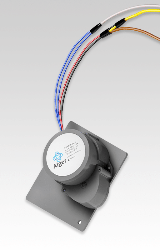
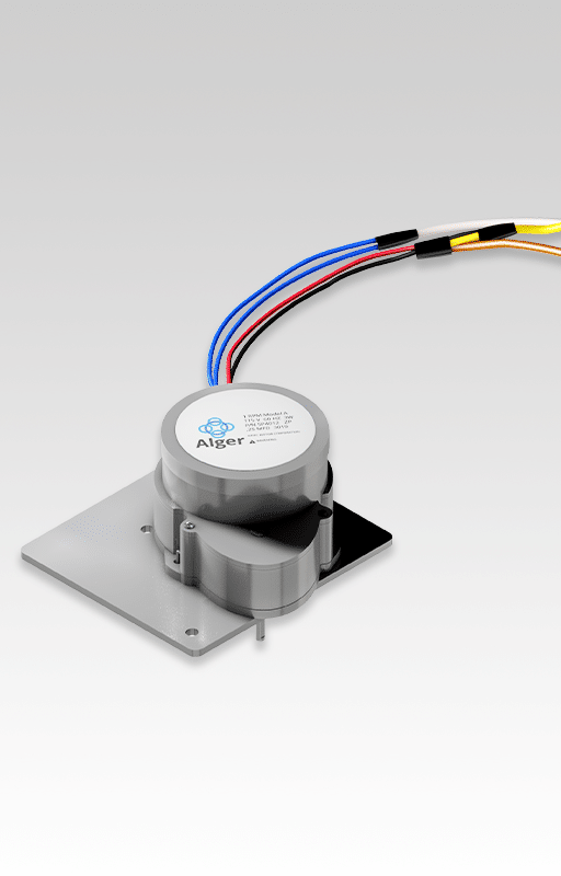
AlgerLight I Replacement Motor Specifications
Replacement Motor - Hurst 1 RMP Model A
115V 60HZ 3 W
Replacing Hurst PC-DA 990497 (external magnetic brake) with Hurst SP4012 (permanent magnet motor)
Weight 3 lbs.
Free Domestic Shipping
110V/220V
Dimensions: W 3 1/2”, L 3 1/2”, H 3”
Power: standard 120-volt (note: for 220-volt Alger-Lights the internal transformers provides necessary 120-volt power via secondary output
AlgerLite 1 Replacement Motor Installation Steps
Determine electrical circuit which supplies power to the AlgerLight 1.
Turn "off" power to AlgerLight 1 by turning “off” the appropriate circuit breaker in your fuse box. This ensures all electrical power going to the AlgerLight 1 has been turned off.
Remove the AlgerLight 1 from ceiling.
If mounting plate has not already been removed from the back of the AlgerLight 1 box, do so by removing the two screws on each side of the AlgerLight 1 cabinet.
Loosen screws connecting wires to bulbs and remove bulbs from the light bar.
Working from the back of the AlgerLight 1 cabinet, use an Allen wrench to loosen set screw holding light bar to motor shaft (Note: After loosening set screw, light bar should swing freely).
Loosen three machine screws securing the old motor to the AlgerLight 1 cabinet (do not remove at this time).
Loosen set screw securing other side of light bar; remove small pivot pin to which the light bar is secured. (Note: care should be taken not to lose this small pin.)
Remove the single machine screw securing the “baffle” to the left side of the light cabinet.
With light bar facing the inside of the cabinet, care¬fully slide the light bar off the motor shaft (Note: it may be necessary to gently pull the light bar towards you at the end opposite the motor so that it clears the flange and can slide completely off the motor shaft.
Remove plastic nut securing motor capacitor (wrapped in electrical tape)
Now remove three machine screws holding old motor and slide baffle and motor out of cabinet.
Please note the following regarding the wiring of the new motor (SP4012): a.) The mounting plate of the new motor has the exact hole pattern of the old motor so must remain attached to new motor. b). The “blue” wire will not be used and can be capped off (wrapped with electrical tape); this wire controls the external brake in the old motor and is not necessary in the new motor which has an internal permanent magnet motor. c). The directional control wires (yellow and brown) will be connected to the same yellow and brown wires.
Cut “blue” wire and cap off with electrical tape (it is not used with new motor).
Cut the yellow and brown wires as shown in the old motor (this also ensures old capacitor is removed).
Connect yellow and brown wires from new motor harness using wire nuts as shown.
The following cut is important: two black wires from the old motor are joined with the two white wires from the transformers (for power) and need to be cut as shown.
Connect white wire from the new motor harness to the two white wires that you just cut.
Note: Old motor should now be completely disconnected from fixture.
Remove three round head machine screws from new motor mounting plate noting the following:
a.) The recess mounted machine screw should not be loosened as this holds the motor to the mounting plate.
b.) Take care that the motor screw holes remain aligned with holes in mounting plate where the round head machine screws were just removed.
Slide “baffle” and motor back into light cabinet and start three motor mounting screws in the threaded motor holes. DO NOT TIGHTEN motor screws at this time.
Secure the “baffle” to the left side of the light cabinet with the single machine screw.
With light bar facing the inside of the cabinet, GENTLY slide the light bar onto the motor shaft with a gentle twisting motion until the opposite end can again be brought into place.
Re-insert small pivot pin through the light bar on side opposite the motor shaft, making sure pin goes through light bar and into mounting bracket.
Tighten the set screw to secure the light bar to the pivot pin. Do not secure light bar to motor shaft at this time; light bar should still swing freely.
Tighten three motor mounting screws
BEFORE securing light bar to motor shaft, the AlgerLight 1 should be mounted back in ceiling (see accompanying notes on reinstallation of the AlgerLight 1).
Reconnect wires going to the AlgerLight 1.
Turn circuit breaker back “on” to restore power to the AlgerLight 1
Using the motor control switch, rotate the motor until the “flat” part of the motor shaft is perpendicular to the ceiling.
Rotate light bar perpendicular to ceiling (i.e., if lights were “on”, the beam would be parallel to the ceiling) and tighten set screw on light bar to the flat part of the motor shaft.
NOTE: Once motor is secured to the motor shaft, EXTREME care must be taken not to rotate the light bar by hand or place any force on the motor shaft assembly. THIS WILL STRIP THE GEARS.
Reinstall bulbs per instructions.
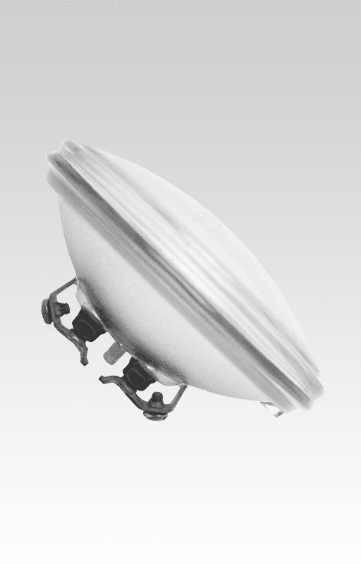
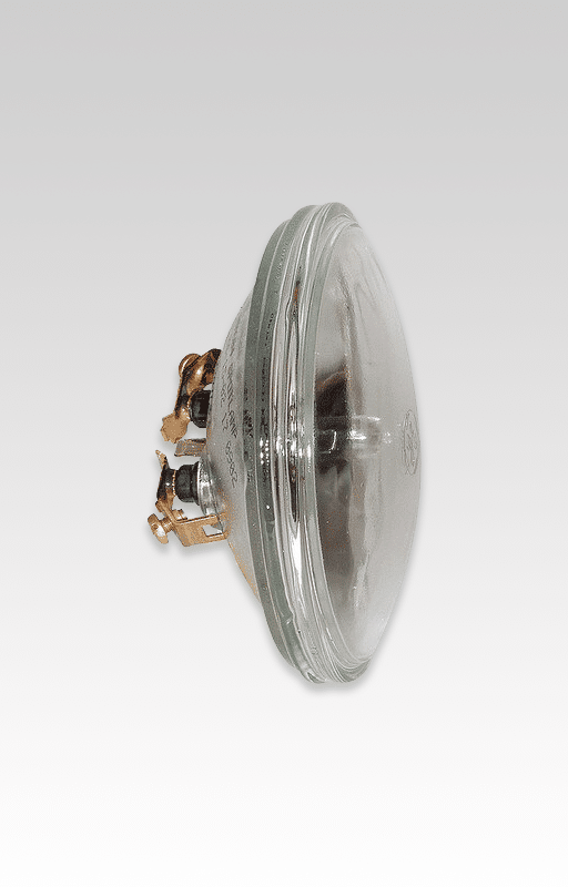
AlgerLight I Bulb
Mfg. SKU: GE4505
Shipping: domestic and international
Packaging: Packaged individually
Weight: 1 pound each
Power: 28V, 50W